Part 3: Bypassing the iTwinkle Controller
This is the third in a series of blog posts about researching and rewiring Christmas lights to work with Arduino devices.
Now that I have a TA screwdriver, let’s see what is inside the iTwinkle controller.
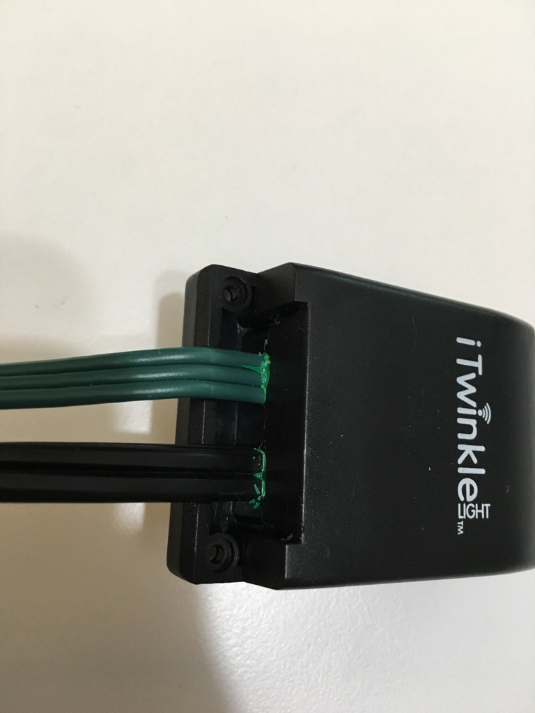
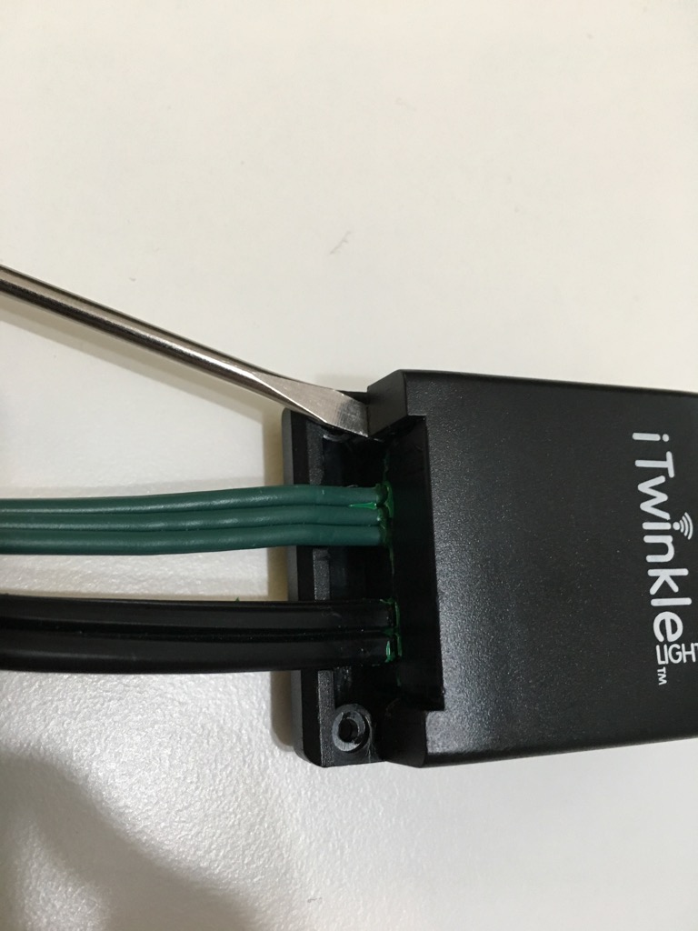 

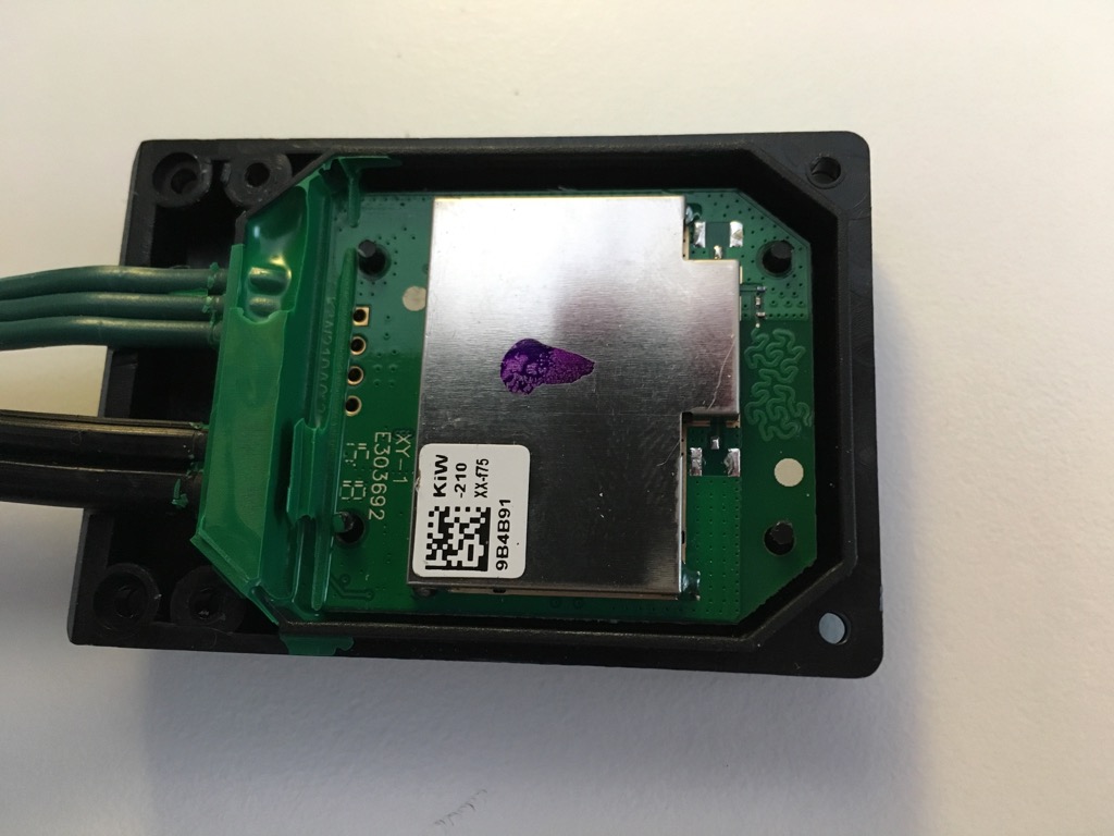
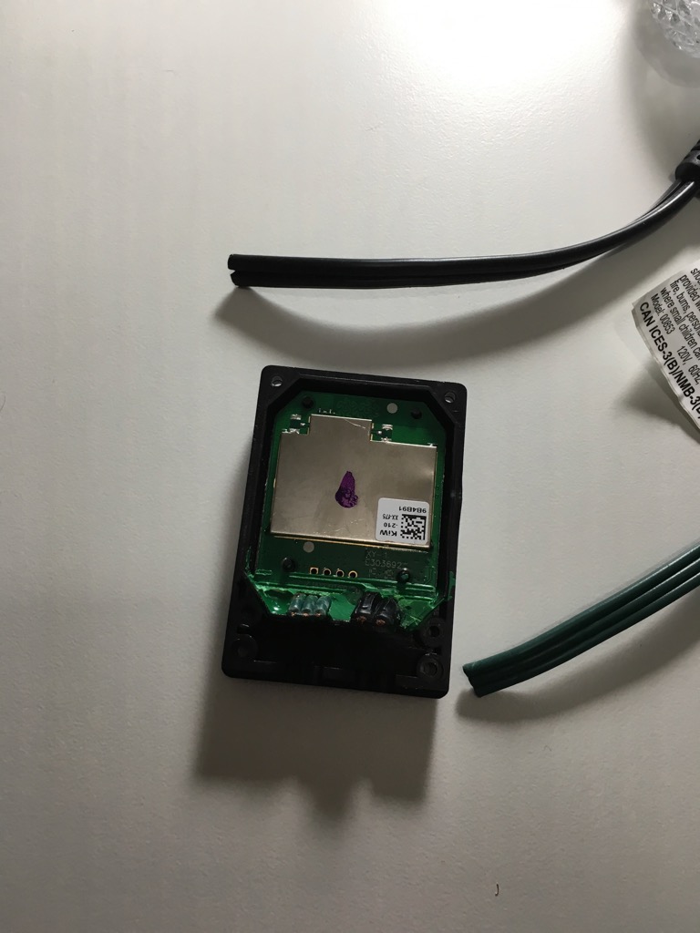
Try as I might, I could not remove that green plastic/glue. So I cut the wires.
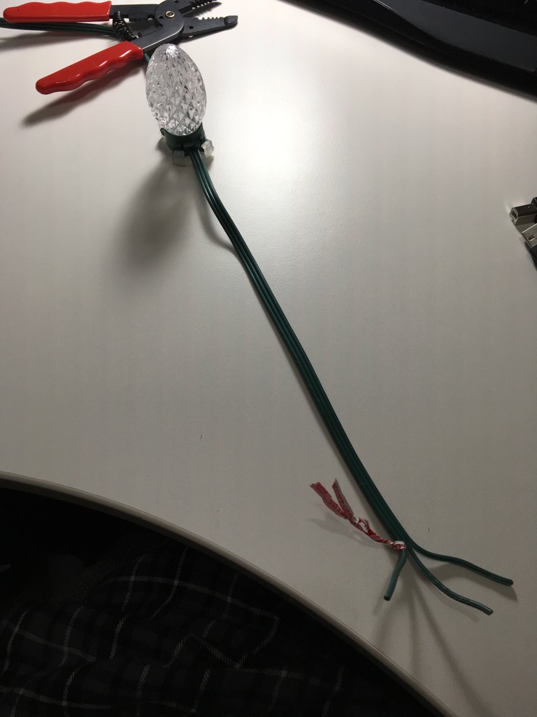
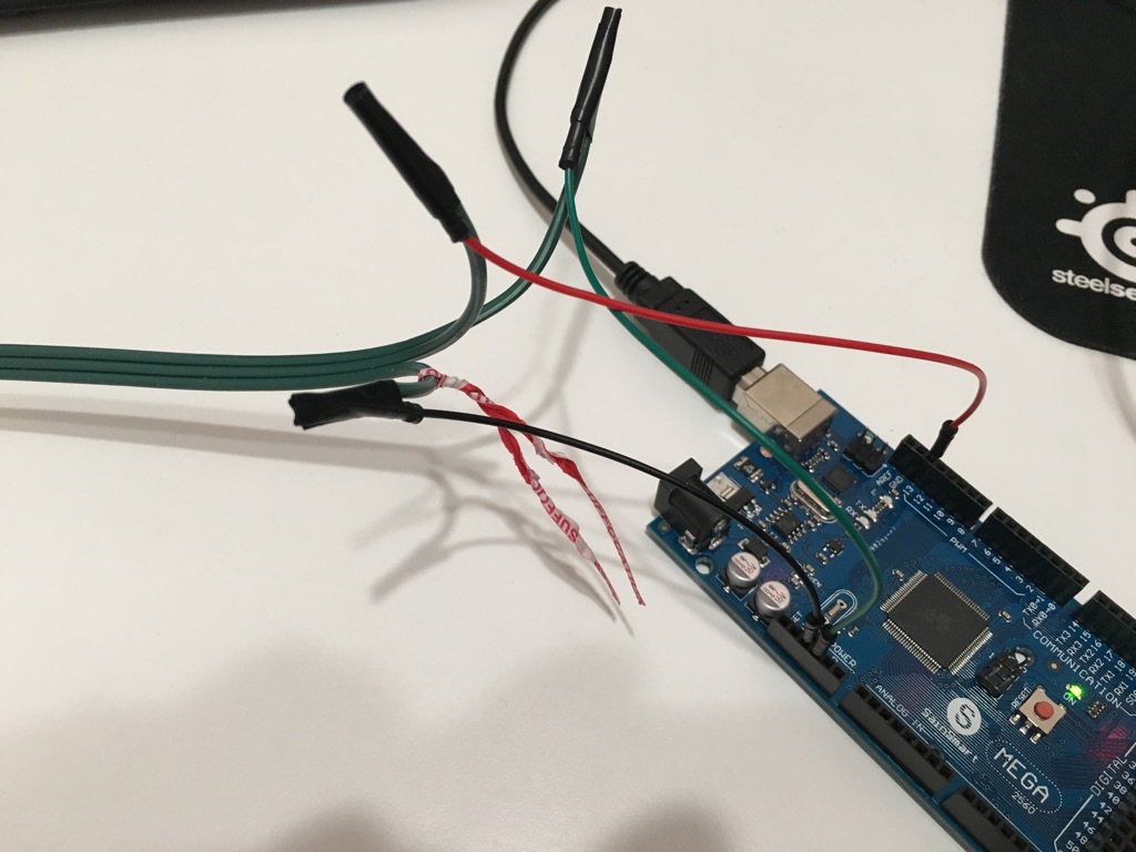
The wires from the lights are V+, Data, and V-. Following the instructions for G35Arduino, I connected LIGHTS V+ to the 5V on the Arduino board, LIGHTS DATA to Pin 13, and LIGHTS V- to Ground. I then plugged the Arduino into my Mac and loaded up the Arduino IDE, and added the G35Arduino library from a ZIP file.
I loaded the Basic Example from the G35Arduino library and changed the number of lights to 36, then uploaded to the Arduino. Within a few seconds, I had a light show going!
I am very impressed. The lights are probably not running at full brightness because the original power brick that came with the lights provided up to 3000 mA, and the USB port on my MacBook Pro is only providing 500 mA. Interestingly, I can plug the Arduino into a portable USB battery and that is enough to run the lights too.
I swapped out the alligator clips and carefully wrapped the copper from the lights around the pin cables, then wrapped those with electrical tape. This is a bit more sturdy.
Primary Project
- Open controller box, disconnect wires to original controller
- Wire power brick to Arduino board, make sure the 5V works
- Wire power and data lines from lights to Arduino board, test connection
- Write Arduino code to do more advanced light programs
- Connect Arduino to WiFi or Bluetooth and setup remote control from iOS or from a Raspberry Pi
- Find a weatherproof housing for the Arduino
- Find weatherproof cables to extend the connections from the Arduino controller to the lights and to the power brick
- Test outside!
According to my plan, I have #1 through #3 complete.
For remote controlling the lights, I am planning on running a small web server on a Raspberry Pi that can send commands to the Arduino over Bluetooth or WiFi. The commands should cover the original iTwinkle light functions, but be accessible through a web browser on my local home network instead of through an app. The main functions should be:
- Set all lights to a colour of my choice, perhaps using a colour wheel?
- Slow or fast fade-in/fade-out of that colour
- Steady colour
- Colour wave (smooth)
- Colour cycling (discrete steps)
- Power on/off
More can be added in the future. Here’s a wild idea: send a command program string to the Arduino where it is decoded and run, instead of hard-coding programs on the Arduino.
I will need a weatherproof housing for the Arduino that has room for the the lights cable and a power cable. I can splice the power cable I cut earlier with a USB Type B cable and have that power the Arduino inside the casing, although I need to make sure there isn’t too much strain on the cable. I will check out one of the nearby hardware stores for housings that might work.
As for the secondary project, I have ordered some 433 MHz radios and they will arrive in the next week. I also ordered a smaller Arduino Uno as the 2560 I am using now is a bit more powerful and larger than I need for this project. I may even downsize to something smaller if I can find something appropriate!