Part 4: Receiving on 433.920MHz
This is the fourth in a series of blog posts about researching and rewiring Christmas lights to work with Arduino devices.
I received the radio modules that I ordered:
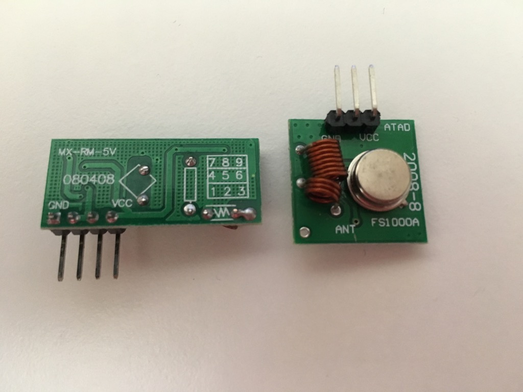
The transmitter module is on the right, the receiver on the left.
I want to capture the signal structure for the RF remote functions. Scott C wrote an excellent tutorial for using these same RF modules to decode and re-play signals for an RF-controlled fan/light.
I connected the receiver to the Arduino as shown below.
| RF Receiver | Arduino |
|---|---|
| GND | GND |
| DATA | (No Connection) |
| DATA | Analog 0 |
| VCC | 3.3V |
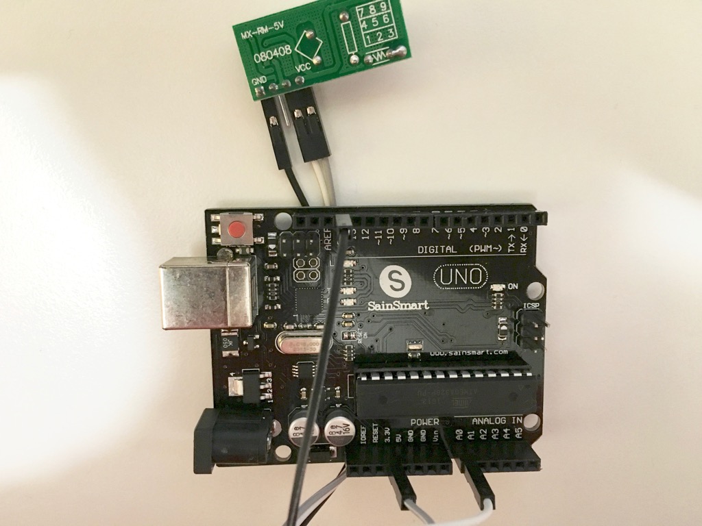
The receiver is connected to 3.3V power as Scott C suggested, to reduce the amount of interference received. This may affect the distance at which the receiver works, but in this case the receiver is only being used temporarily to decode the remote signals.
I then loaded a modified version of Scott’s code into the Arduino IDE:
/*
  RF Remote Capture sketch
     Written by ScottC 24 Jun 2014
     Modified by James Badger 10 Nov 2016
     Arduino IDE version 1.6.11
     Website: http://arduinobasics.blogspot.com
     Receiver: XY-MK-5V
     Description: Use Arduino to Receive RF Remote signal
 ------------------------------------------------------------- */

const int dataSize = 500;    // Arduino memory is limited (max=1700)
byte storedData[dataSize];   // Create an array to store the data
#define ledPin 13            // Onboard LED = digital pin 13
#define rfReceivePin A0      // RF Receiver data pin = Analog pin 0
const unsigned int upperThreshold = 100;  // upper threshold value
const unsigned int lowerThreshold = 80;  // lower threshold value
int maxSignalLength = 255;       // Set the maximum length of the signal
int dataCounter = 0;             // Variable to measure the length of the signal
unsigned long startTime = 0;       // Variable to record the start time
unsigned long endTime = 0;         // Variable to record the end time
unsigned long signalDuration = 0;  // Variable to record signal reading time


void setup() {
  Serial.begin(9600);
  pinMode(ledPin, OUTPUT);

  /* The following code will only run ONCE --------------
  ---Press the reset button on the Arduino to run again-- */

  while(analogRead(rfReceivePin) < 1) {
      // Wait here until a LOW signal is received
      startTime = micros();  // Update start time with every cycle.
  }
  digitalWrite(ledPin, HIGH);  // Turn LED ON

  // Read and store the rest of the signal into the storedData array
  for(int i = 0; i < dataSize; i = i + 2) {
    // Identify the length of the HIGH signal---------------HIGH
    dataCounter = 0; // reset the counter
    while(analogRead(rfReceivePin) > upperThreshold && dataCounter < maxSignalLength) {
      dataCounter++;
    }
    storedData[i] = dataCounter;

    // Identify the length of the LOW signal---------------LOW
    dataCounter = 0; // reset the counter
    while(analogRead(rfReceivePin) < lowerThreshold && dataCounter < maxSignalLength) {
      dataCounter++;
    }
    storedData[i+1] = dataCounter;

    // Any readings between the two threshold values will be ignored.
    // The LOW or HIGH signal length must be less than the variable "maxSignalLength"
    // otherwise it will be truncated. All of the HIGH signals and LOW signals combined
    // must not exceed the variable "dataSize", otherwise it will be truncated.
    // The maximum number of signals is 1700 - if you try to extend this variable to a higher
    // number than 1700 - then the Arduino will freeze up and sketch will not work.
    //-------------------------------------------------------------
  }

  endTime = micros();  // Record the end time of the read period.
  signalDuration = endTime - startTime;

  digitalWrite(ledPin, LOW); // Turn LED OFF

  // Send report to the Serial Monitor
  Serial.println("=====================");
  Serial.print("Read duration: ");
  Serial.print(signalDuration);
  Serial.println(" microseconds");
  Serial.println("=====================");
  Serial.println("HIGH,LOW");
  delay(20);
  for(int i = 0; i < dataSize; i = i + 2) {
    Serial.print(storedData[i]);
    Serial.print(",");
    Serial.println(storedData[i+1]);
    delay(20);
  }
}

void loop() {
  //Do nothing here
}
There was a minor mix up in the original code where signals with low numbers (close to zero) were called “HIGH”, and vice versa. This isn’t quite correct as LOW signals should give lower analog readings and HIGH signals should give higher analog readings. I switched the code above to label the resulting data correctly.
Next I had to run the program once for each remote function: “Power On”, “Power Off”, “Function Cycle”, and “Sync”. I turned opened the Serial Monitor and uploaded the program, waited until the LED turned on, then pressed the Power button on the remote to turn the lights on. I then repeated the process with Power Off, Cycle Function, and Sync, producing the following four files.
In each file, a definitive repeated pattern shows up although the pattern is different in each file. Each number represents the duration of a HIGH or LOW signal that was detected. Each pattern repeats itself multiple times; 5 for Power ON, 6 for Power OFF, 3 for CYCLE, and 5 for SYNC. This may be caused by how long I held down the buttons on the remote, but for each case the signals are typically repeated.
If I take the Power On set and put the results into a table, the pattern is even more apparent.
| H | L | H | L | H | L | H | L | H | L |
|---|---|---|---|---|---|---|---|---|---|
| 26 | 13 | 26 | 12 | 25 | 13 | 26 | 13 | 26 | 12 |
| 3 | 4 | 4 | 3 | 3 | 4 | 3 | 4 | 4 | 3 |
| 3 | 8 | 4 | 8 | 3 | 8 | 3 | 8 | 4 | 8 |
| 4 | 3 | 3 | 4 | 4 | 4 | 4 | 3 | 3 | 4 |
| 4 | 8 | 3 | 8 | 3 | 8 | 4 | 8 | 3 | 8 |
| 3 | 8 | 4 | 8 | 3 | 9 | 3 | 8 | 4 | 8 |
| 4 | 3 | 3 | 4 | 3 | 4 | 4 | 3 | 3 | 4 |
| 4 | 3 | 3 | 4 | 3 | 4 | 4 | 3 | 3 | 4 |
| 4 | 8 | 3 | 9 | 3 | 8 | 4 | 8 | 3 | 9 |
| 3 | 8 | 3 | 8 | 4 | 8 | 3 | 8 | 3 | 8 |
| 4 | 8 | 3 | 9 | 3 | 8 | 4 | 8 | 3 | 9 |
| 3 | 4 | 3 | 4 | 4 | 3 | 3 | 4 | 3 | 4 |
| 3 | 8 | 3 | 8 | 4 | 8 | 3 | 9 | 3 | 8 |
| 4 | 4 | 4 | 3 | 3 | 4 | 3 | 4 | 4 | 3 |
| 3 | 4 | 4 | 3 | 3 | 4 | 3 | 4 | 4 | 3 |
| 3 | 4 | 4 | 3 | 3 | 4 | 3 | 4 | 4 | 3 |
| 3 | 4 | 4 | 3 | 3 | 4 | 3 | 4 | 4 | 3 |
| 3 | 71 | 4 | 71 | 3 | 71 | 3 | 71 | 4 | 255 |
As with Scott’s tutorial, some of the numbers are estimates and can be smoothed a bit — for example, 3 durations replaced by 4 and so on. With some formatting, the signal becomes obvious:
| H | L | H | L | H | L | H | L | H | L |
|---|---|---|---|---|---|---|---|---|---|
| 26 | 12 | 26 | 12 | 26 | 12 | 26 | 12 | 26 | 12 |
| 4 | 4 | 4 | 4 | 4 | 4 | 4 | 4 | 4 | 4 |
| 4 | 8 | 4 | 8 | 4 | 8 | 4 | 8 | 4 | 8 |
| 4 | 4 | 4 | 4 | 4 | 4 | 4 | 4 | 4 | 4 |
| 4 | 8 | 4 | 8 | 4 | 8 | 4 | 8 | 4 | 8 |
| 4 | 8 | 4 | 8 | 4 | 8 | 4 | 8 | 4 | 8 |
| 4 | 4 | 4 | 4 | 4 | 4 | 4 | 4 | 4 | 4 |
| 4 | 4 | 4 | 4 | 4 | 4 | 4 | 4 | 4 | 4 |
| 4 | 8 | 4 | 8 | 4 | 8 | 4 | 8 | 4 | 8 |
| 4 | 8 | 4 | 8 | 4 | 8 | 4 | 8 | 4 | 8 |
| 4 | 8 | 4 | 8 | 4 | 8 | 4 | 8 | 4 | 8 |
| 4 | 4 | 4 | 4 | 4 | 4 | 4 | 4 | 4 | 4 |
| 4 | 8 | 4 | 8 | 4 | 8 | 4 | 8 | 4 | 8 |
| 4 | 4 | 4 | 4 | 4 | 4 | 4 | 4 | 4 | 4 |
| 4 | 4 | 4 | 4 | 4 | 4 | 4 | 4 | 4 | 4 |
| 4 | 4 | 4 | 4 | 4 | 4 | 4 | 4 | 4 | 4 |
| 4 | 4 | 4 | 4 | 4 | 4 | 4 | 4 | 4 | 4 |
| 4 | 71 | 4 | 71 | 4 | 71 | 4 | 71 | 4 | 71 |
And with the remaining signals, their specific commands are displayed.
| H | L | H | L | H | L | H | L | H | L | H | L |
|---|---|---|---|---|---|---|---|---|---|---|---|
| 26 | 12 | 26 | 12 | 26 | 12 | 26 | 12 | 26 | 12 | 26 | 12 |
| 4 | 4 | 4 | 4 | 4 | 4 | 4 | 4 | 4 | 4 | 4 | 4 |
| 4 | 8 | 4 | 8 | 4 | 8 | 4 | 8 | 4 | 8 | 4 | 8 |
| 4 | 4 | 4 | 4 | 4 | 4 | 4 | 4 | 4 | 4 | 4 | 4 |
| 4 | 8 | 4 | 8 | 4 | 8 | 4 | 8 | 4 | 8 | 4 | 8 |
| 4 | 8 | 4 | 8 | 4 | 8 | 4 | 8 | 4 | 8 | 4 | 8 |
| 4 | 4 | 4 | 4 | 4 | 4 | 4 | 4 | 4 | 4 | 4 | 4 |
| 4 | 4 | 4 | 4 | 4 | 4 | 4 | 4 | 4 | 4 | 4 | 4 |
| 4 | 8 | 4 | 8 | 4 | 8 | 4 | 8 | 4 | 8 | 4 | 8 |
| 4 | 8 | 4 | 8 | 4 | 8 | 4 | 8 | 4 | 8 | 4 | 8 |
| 4 | 8 | 4 | 8 | 4 | 8 | 4 | 8 | 4 | 8 | 4 | 8 |
| 4 | 4 | 4 | 4 | 4 | 4 | 4 | 4 | 4 | 4 | 4 | 4 |
| 4 | 8 | 4 | 8 | 4 | 8 | 4 | 8 | 4 | 8 | 4 | 8 |
| 4 | 4 | 4 | 4 | 4 | 4 | 4 | 4 | 4 | 4 | 4 | 4 |
| 4 | 4 | 4 | 4 | 4 | 4 | 4 | 4 | 4 | 4 | 4 | 4 |
| 4 | 4 | 4 | 4 | 4 | 4 | 4 | 4 | 4 | 4 | 4 | 4 |
| 4 | 8 | 4 | 8 | 4 | 8 | 4 | 8 | 4 | 8 | 4 | 8 |
| 4 | 71 | 4 | 71 | 4 | 71 | 4 | 71 | 4 | 71 | 4 | 71 |
| H | L | H | L | H | L |
|---|---|---|---|---|---|
| 26 | 12 | 26 | 12 | 26 | 12 |
| 4 | 4 | 4 | 4 | 4 | 4 |
| 4 | 8 | 4 | 8 | 4 | 8 |
| 4 | 4 | 4 | 4 | 4 | 4 |
| 4 | 8 | 4 | 8 | 4 | 8 |
| 4 | 8 | 4 | 8 | 4 | 8 |
| 4 | 4 | 4 | 4 | 4 | 4 |
| 4 | 4 | 4 | 4 | 4 | 4 |
| 4 | 8 | 4 | 8 | 4 | 8 |
| 4 | 8 | 4 | 8 | 4 | 8 |
| 4 | 8 | 4 | 8 | 4 | 8 |
| 4 | 8 | 4 | 8 | 4 | 8 |
| 4 | 4 | 4 | 4 | 4 | 4 |
| 4 | 8 | 4 | 8 | 4 | 8 |
| 4 | 8 | 4 | 8 | 4 | 8 |
| 4 | 4 | 4 | 4 | 4 | 4 |
| 4 | 4 | 4 | 4 | 4 | 4 |
| 4 | 71 | 4 | 71 | 4 | 71 |
| H | L | H | L | H | L | H | L | H | L |
|---|---|---|---|---|---|---|---|---|---|
| 26 | 12 | 26 | 12 | 26 | 12 | 26 | 12 | 26 | 12 |
| 4 | 4 | 4 | 4 | 4 | 4 | 4 | 4 | 4 | 4 |
| 4 | 4 | 4 | 4 | 4 | 4 | 4 | 4 | 4 | 4 |
| 4 | 8 | 4 | 8 | 4 | 8 | 4 | 8 | 4 | 8 |
| 4 | 8 | 4 | 8 | 4 | 8 | 4 | 8 | 4 | 8 |
| 4 | 4 | 4 | 4 | 4 | 4 | 4 | 4 | 4 | 4 |
| 4 | 8 | 4 | 8 | 4 | 8 | 4 | 8 | 4 | 8 |
| 4 | 8 | 4 | 8 | 4 | 8 | 4 | 8 | 4 | 8 |
| 4 | 8 | 4 | 8 | 4 | 8 | 4 | 8 | 4 | 8 |
| 4 | 4 | 4 | 4 | 4 | 4 | 4 | 4 | 4 | 4 |
| 4 | 4 | 4 | 4 | 4 | 4 | 4 | 4 | 4 | 4 |
| 4 | 4 | 4 | 4 | 4 | 4 | 4 | 4 | 4 | 4 |
| 4 | 8 | 4 | 8 | 4 | 8 | 4 | 8 | 4 | 8 |
| 4 | 8 | 4 | 8 | 4 | 8 | 4 | 8 | 4 | 8 |
| 4 | 8 | 4 | 8 | 4 | 8 | 4 | 8 | 4 | 8 |
| 4 | 4 | 4 | 4 | 4 | 4 | 4 | 4 | 4 | 4 |
| 4 | 4 | 4 | 4 | 4 | 4 | 4 | 4 | 4 | 4 |
| 4 | 71 | 4 | 71 | 4 | 71 | 4 | 71 | 4 | 71 |
The next step was creating an Arduino program that can repeat these patterns, although the specific length of each signal is not yet known, only the relative lengths were captured in the receiver program above. To determine the actual delay length the codes will have to be tried repeatedly with an increasing delay to find the ones that actually activate the lights.
To send codes I connected the transmitter to the Arduino as shown below.
| RF Receiver | Arduino |
|---|---|
| GND | GND |
| DATA | Digital 4 |
| VCC | 5V |
Next I uploaded the following program, based on the one Scott C used in his tutorial.
/*
  Transmit sketch - RF Calibration
     Written by ScottC 17 July 2014
     Edited by James Badger 10 November 2016
     Arduino IDE version 1.6.11
     Website: http://arduinobasics.blogspot.com
     Transmitter: FS1000A/XY-FST
     Description: A simple sketch used to calibrate RF transmission.
 ------------------------------------------------------------- */

#define rfTransmitPin 4  // RF Transmitter pin = digital pin 4
#define ledPin 13        // Onboard LED = digital pin 13

const int codeSize = 18;
int powerOnSignal[18][2] = {
  {26,12},
  {4,4},
  {4,8},
  {4,4},
  {4,8},
  {4,8},
  {4,4},
  {4,4},
  {4,8},
  {4,8},
  {4,8},
  {4,4},
  {4,8},
  {4,4},
  {4,4},
  {4,4},
  {4,4},
  {4,71}
};
int timeDelay = 50; // The variable used to calibrate the RF signal lengths.

void setup() {
  Serial.begin(9600);        // Turn the Serial Protocol ON
  pinMode(rfTransmitPin, OUTPUT);   //Transmit pin is an output
  pinMode(ledPin, OUTPUT);

  // LED initialisation sequence - gives us some time to get ready
  digitalWrite(ledPin, HIGH);
  delay(3000);
  digitalWrite(ledPin, LOW);
  delay(1000);
}

void loop() {
  Serial.print("Delay: ");
  Serial.print(timeDelay);
  Serial.print(" microseconds\n");
  transmitCode();  // transmit the code to RF receiver on the lights

  timeDelay += 10; // Increment the timeDelay by 10 microseconds with every transmission
  delay(5000); // Each transmission will be about 5 seconds apart.
}

void transmitCode() {
  // The LED will be turned on to create a visual signal transmission indicator.
  digitalWrite(ledPin, HIGH);

  // initialise the variables
  int highLength = 0;
  int lowLength = 0;

  // The signal is transmitted 6 times in succession - this may vary with your remote.
  int time = millis();
  for(int j = 0; j < 6; j++) {
    for(int i = 0; i < codeSize; i++) {
      highLength = powerOnSignal[i][0];
      lowLength = powerOnSignal[i][1];

       /* Transmit a HIGH signal - the duration of transmission will be determined
          by the highLength and timeDelay variables */
       digitalWrite(rfTransmitPin, HIGH);
       delayMicroseconds(highLength * timeDelay);

       /* Transmit a LOW signal - the duration of transmission will be determined
          by the lowLength and timeDelay variables */
       digitalWrite(rfTransmitPin,LOW);
       delayMicroseconds(lowLength * timeDelay);
    }
  }
  int duration = millis() - time;
  Serial.print("Duration: ");
  Serial.print(duration);
  Serial.print(" milliseconds\n");
  //Turn the LED off after the code has been transmitted.
  digitalWrite(ledPin, LOW);
}
I embedded the “Power On” code directly in a 2D array to simplify the code. I will use remote code aliases later when the other codes are needed. I updated the wait between signal tests to 5 seconds as I had to use the real remote to turn the lights off between tests if the Arduino had turned the lights on.
I ran the program and opened the Serial Monitor to monitor the delays. I found that delays from 100 to 140 microseconds all worked and turned on the lights! Splitting that down the middle would give 120 microseconds.
With that in hand I wrote a program that takes input over Serial and uses that to control the lights.
// Remote Control Sketch
#define rfTransmitPin 4
#define ledPin 13

const int codeSize = 18;
int codeTable[4][2] = {
  {4,4},  // 0
  {4,8},  // 1
  {4,71}, // 2
  {26,12} // 3
};
int powerOn[codeSize] = {3,0,1,0,1,1,0,0,1,1,1,0,1,0,0,0,0,2};
int powerOff[codeSize] = {3,0,1,0,1,1,0,0,1,1,1,0,1,0,0,0,1,2};
int cycle[codeSize] = {3,0,1,0,1,1,0,0,1,1,1,1,0,1,1,0,0,2};
int sync[codeSize] = {3,0,0,1,1,0,1,1,1,0,0,0,1,1,1,0,0,2};

// The length of the RF signals, in microseconds
int timeDelay = 120;
int incomingByte = 0;
int codeAlias;
int highLength;
int lowLength;

void setup() {
  Serial.begin(9600);
  pinMode(rfTransmitPin, OUTPUT);
  pinMode(ledPin, OUTPUT);

  digitalWrite(ledPin, HIGH);
  delay(3000);
  digitalWrite(ledPin, LOW);
  delay(1000);
  Serial.println("Ready to receive commands.");
  Serial.read();
}

void loop() {
  if (Serial.available() >= 0) {
    incomingByte = Serial.read();

    switch(incomingByte) {
      case '1':
      Serial.println("Power on!");
      transmitCode(powerOn);
      break;
      case '0':
      Serial.println("Power off!");
      transmitCode(powerOff);
      break;
      case 'C':
      Serial.println("Cycle function!");
      transmitCode(cycle);
      break;
      case 'S':
      Serial.println("Sync!");
      transmitCode(sync);
      break;
      default:
      break;
    }
  }
}

void transmitCode(int *code) {
  for (int i = 0; i < codeSize; i++) {
    codeAlias = code[i];

    highLength = codeTable[codeAlias][0];
    lowLength = codeTable[codeAlias][1];

     digitalWrite(rfTransmitPin, HIGH);
     delayMicroseconds(highLength * timeDelay);

     digitalWrite(rfTransmitPin, LOW);
     delayMicroseconds(lowLength * timeDelay);
  }
}
By typing “1”, “0”, “C”, or “S” in the Serial Monitor console I could then send the commands to the lights. This worked great, except for one thing: The cycle function only loads a specific lights program instead of cycling them. This could mean that each lights program has its own RF code pattern!
I loaded the receiver program again, and ran it a few times to capture the output of the functions button on the remote. The box for the Home Collection lights advertises 8 different programs, so I am assuming that if I collect 9 remote function signals that I should loop around and collect the first one twice.
| Function | Code Pairs | |||||||||||||||||
|---|---|---|---|---|---|---|---|---|---|---|---|---|---|---|---|---|---|---|
| Function 1 | 26,12 | 4,4 | 4,8 | 4,4 | 4,8 | 4,8 | 4,4 | 4,4 | 4,8 | 4,8 | 4,8 | 4,8 | 4,4 | 4,4 | 4,4 | 4,4 | 4,4 | 4,71 |
| Function 2 | 26,12 | 4,4 | 4,8 | 4,4 | 4,8 | 4,8 | 4,4 | 4,4 | 4,8 | 4,8 | 4,8 | 4,8 | 4,4 | 4,4 | 4,4 | 4,4 | 4,8 | 4,71 |
| Function 3 | 26,12 | 4,4 | 4,8 | 4,4 | 4,8 | 4,8 | 4,4 | 4,4 | 4,8 | 4,8 | 4,8 | 4,8 | 4,4 | 4,4 | 4,4 | 4,8 | 4,4 | 4,71 |
| Function 4 | 26,12 | 4,4 | 4,8 | 4,4 | 4,8 | 4,8 | 4,4 | 4,4 | 4,8 | 4,8 | 4,8 | 4,8 | 4,4 | 4,4 | 4,4 | 4,8 | 4,8 | 4,71 |
| Function 5 | 26,12 | 4,4 | 4,8 | 4,4 | 4,8 | 4,8 | 4,4 | 4,4 | 4,8 | 4,8 | 4,8 | 4,8 | 4,4 | 4,4 | 4,8 | 4,4 | 4,4 | 4,71 |
| Function 6 | 26,12 | 4,4 | 4,8 | 4,4 | 4,8 | 4,8 | 4,4 | 4,4 | 4,8 | 4,8 | 4,8 | 4,8 | 4,4 | 4,4 | 4,8 | 4,4 | 4,8 | 4,71 |
| Function 7 | 26,12 | 4,4 | 4,8 | 4,4 | 4,8 | 4,8 | 4,4 | 4,4 | 4,8 | 4,8 | 4,8 | 4,8 | 4,4 | 4,4 | 4,8 | 4,8 | 4,4 | 4,71 |
| Function 8 | 26,12 | 4,4 | 4,8 | 4,4 | 4,8 | 4,8 | 4,4 | 4,4 | 4,8 | 4,8 | 4,8 | 4,8 | 4,4 | 4,4 | 4,8 | 4,8 | 4,8 | 4,71 |
| Function 9 | 26,12 | 4,4 | 4,8 | 4,4 | 4,8 | 4,8 | 4,4 | 4,4 | 4,8 | 4,8 | 4,8 | 4,8 | 4,4 | 4,8 | 4,4 | 4,4 | 4,4 | 4,71 |
| Function 10 | 26,12 | 4,4 | 4,8 | 4,4 | 4,8 | 4,8 | 4,4 | 4,4 | 4,8 | 4,8 | 4,8 | 4,8 | 4,4 | 4,8 | 4,4 | 4,4 | 4,8 | 4,71 |
| Function 11 | 26,12 | 4,4 | 4,8 | 4,4 | 4,8 | 4,8 | 4,4 | 4,4 | 4,8 | 4,8 | 4,8 | 4,8 | 4,4 | 4,8 | 4,4 | 4,8 | 4,4 | 4,71 |
| Function 12 | 26,12 | 4,4 | 4,8 | 4,4 | 4,8 | 4,8 | 4,4 | 4,4 | 4,8 | 4,8 | 4,8 | 4,8 | 4,4 | 4,8 | 4,4 | 4,8 | 4,8 | 4,71 |
| Function 13 | 26,12 | 4,4 | 4,8 | 4,4 | 4,8 | 4,8 | 4,4 | 4,4 | 4,8 | 4,8 | 4,8 | 4,8 | 4,4 | 4,8 | 4,8 | 4,4 | 4,4 | 4,71 |
| Function 14 | 26,12 | 4,4 | 4,8 | 4,4 | 4,8 | 4,8 | 4,4 | 4,4 | 4,8 | 4,8 | 4,8 | 4,8 | 4,4 | 4,8 | 4,8 | 4,4 | 4,8 | 4,71 |
| Function 15 | 26,12 | 4,4 | 4,8 | 4,4 | 4,8 | 4,8 | 4,4 | 4,4 | 4,8 | 4,8 | 4,8 | 4,8 | 4,4 | 4,8 | 4,8 | 4,8 | 4,4 | 4,71 |
| Function 16 | 26,12 | 4,4 | 4,8 | 4,4 | 4,8 | 4,8 | 4,4 | 4,4 | 4,8 | 4,8 | 4,8 | 4,8 | 4,4 | 4,8 | 4,8 | 4,8 | 4,8 | 4,71 |
| Function 17 | 26,12 | 4,4 | 4,8 | 4,4 | 4,8 | 4,8 | 4,4 | 4,4 | 4,8 | 4,8 | 4,8 | 4,8 | 4,4 | 4,4 | 4,4 | 4,4 | 4,4 | 4,71 |
As seen in the table above, there were more than eight codes and actually sixteen in total. You may have noticed the progression on the right side of the code table. Replacing blue cells with 0 and green cells with 1 produces the following sequence:
00000
00001
00010
00011
00100
...
This is binary for 0, 1, 2, 3, and so on. I updated my control program to support these codes:
// Remote Control Sketch
#define rfTransmitPin 4
#define ledPin 13

const int codeSize = 18;
int codeTable[4][2] = {
  {4,4},  // 0
  {4,8},  // 1
  {4,71}, // 2
  {26,12} // 3
};
int powerOn[codeSize] = {3,0,1,0,1,1,0,0,1,1,1,0,1,0,0,0,0,2};
int powerOff[codeSize] = {3,0,1,0,1,1,0,0,1,1,1,0,1,0,0,0,1,2};
int sync[codeSize] = {3,0,0,1,1,0,1,1,1,0,0,0,1,1,1,0,0,2};
int programs[16][codeSize] = {
  {3,0,1,0,1,1,0,0,1,1,1,1,0,0,0,0,0,2},
  {3,0,1,0,1,1,0,0,1,1,1,1,0,0,0,0,1,2},
  {3,0,1,0,1,1,0,0,1,1,1,1,0,0,0,1,0,2},
  {3,0,1,0,1,1,0,0,1,1,1,1,0,0,0,1,1,2},
  {3,0,1,0,1,1,0,0,1,1,1,1,0,0,1,0,0,2},
  {3,0,1,0,1,1,0,0,1,1,1,1,0,0,1,0,1,2},
  {3,0,1,0,1,1,0,0,1,1,1,1,0,0,1,1,0,2},
  {3,0,1,0,1,1,0,0,1,1,1,1,0,0,1,1,1,2},
  {3,0,1,0,1,1,0,0,1,1,1,1,0,1,0,0,0,2},
  {3,0,1,0,1,1,0,0,1,1,1,1,0,1,0,0,1,2},
  {3,0,1,0,1,1,0,0,1,1,1,1,0,1,0,1,0,2},
  {3,0,1,0,1,1,0,0,1,1,1,1,0,1,0,1,1,2},
  {3,0,1,0,1,1,0,0,1,1,1,1,0,1,1,0,0,2},
  {3,0,1,0,1,1,0,0,1,1,1,1,0,1,1,0,1,2},
  {3,0,1,0,1,1,0,0,1,1,1,1,0,1,1,1,0,2},
  {3,0,1,0,1,1,0,0,1,1,1,1,0,1,1,1,1,2}
};

// The length of the RF signals, in microseconds
int timeDelay = 120;
char inBuffer[4];
int codeAlias;
int highLength;
int lowLength;
int programID;

void setup() {
  Serial.begin(9600);
  pinMode(rfTransmitPin, OUTPUT);
  pinMode(ledPin, OUTPUT);

  digitalWrite(ledPin, HIGH);
  delay(3000);
  digitalWrite(ledPin, LOW);
  delay(1000);
  Serial.println("Ready to receive commands.");
  Serial.read();
}

void loop() {
  if (Serial.available() > 0) {
    Serial.readBytes(inBuffer, 4);

    switch(inBuffer[0]) {
      case '1':
      Serial.println("Power on!");
      transmitCode(powerOn);
      break;
      case '0':
      Serial.println("Power off!");
      transmitCode(powerOff);
      break;
      case 'P':
      // Check if input is 1 followed by 0 through 5
      if (inBuffer[1] == '1' && inBuffer[2] >= 48 && inBuffer[2] <= 53) {
        programID = 10 + inBuffer[2] - 48;
        Serial.print("Running Program: ");
        Serial.println(programID, DEC);
        transmitCode(programs[programID]);
      } else if (inBuffer[1] >= 48 && inBuffer[1] <= 57) {
        programID = inBuffer[1] - 48;
        Serial.print("Running Program: ");
        Serial.println(programID, DEC);
        transmitCode(programs[programID]);
      } else {
        Serial.println(inBuffer[1]);
        Serial.println("Invalid program number.");
      }
      break;
      case 'S':
      Serial.println("Sync!");
      transmitCode(sync);
      break;
      default:
      break;
    }
  }
  inBuffer[0] = 0;
}

void transmitCode(int *code) {
  for (int j = 0; j < 6; j++) {
    for (int i = 0; i < codeSize; i++) {
      codeAlias = code[i];

      highLength = codeTable[codeAlias][0];
      lowLength = codeTable[codeAlias][1];

       digitalWrite(rfTransmitPin, HIGH);
       delayMicroseconds(highLength * timeDelay);

       digitalWrite(rfTransmitPin, LOW);
       delayMicroseconds(lowLength * timeDelay);
    }
  }
}
Upon testing the codes, here are their actual names:
| Function ID | Function Activity |
|---|---|
| 0 | Combination |
| 1 | Steady On |
| 2 | 2Hz Blink |
| 3 | Fast Blink |
| 4 | Slow Fade-in/Fade-out |
| 5 | Fast Fade-in/Fade-out |
| 6 | Blink-Blink-Steady |
| 7 | Discrete Fade-in/Fade-out |
| 8 | Combination |
| 9 | Steady On |
| 10 | 2Hz Blink |
| 11 | Fast Blink |
| 12 | Slow Fade-in/Fade-out |
| 13 | Fast Fade-in/Fade-out |
| 14 | Blink-Blink-Steady |
| 15 | Discrete Fade-in/Fade-out |
It looks like the codes are repeated and while the remote and controller could support up to 16 functions, only 8 have been programmed.
So what’s next?
Secondary Project
Get 433.920 MHz radio boards for ArduinoTest HC lights remote with Arduino and radio receiver to determine signals for controlling HC lightsUse Arduino and radio transmitter to simulate the remote and control the lights- Connect Arduino to WiFi or Bluetooth and setup remote control from iOS or from a Raspberry Pi
- Find a housing for the Arduino — it is wireless so it doesn’t need to go outdoors but it will need power
- Test range of the remote, then the range of the Arduino
- Get antenna if necessary
- Set up lights outdoors, then control them from indoors!
I have an ESP8266 WiFi module that I can connect to the Arduino and run a small TCP server, allowing me to send commands over my local network and control the lights. I could also program the ESP8266 directly, although I don’t want to deal with breadboards yet.